
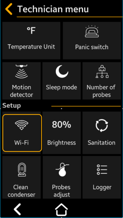
Technician Menu
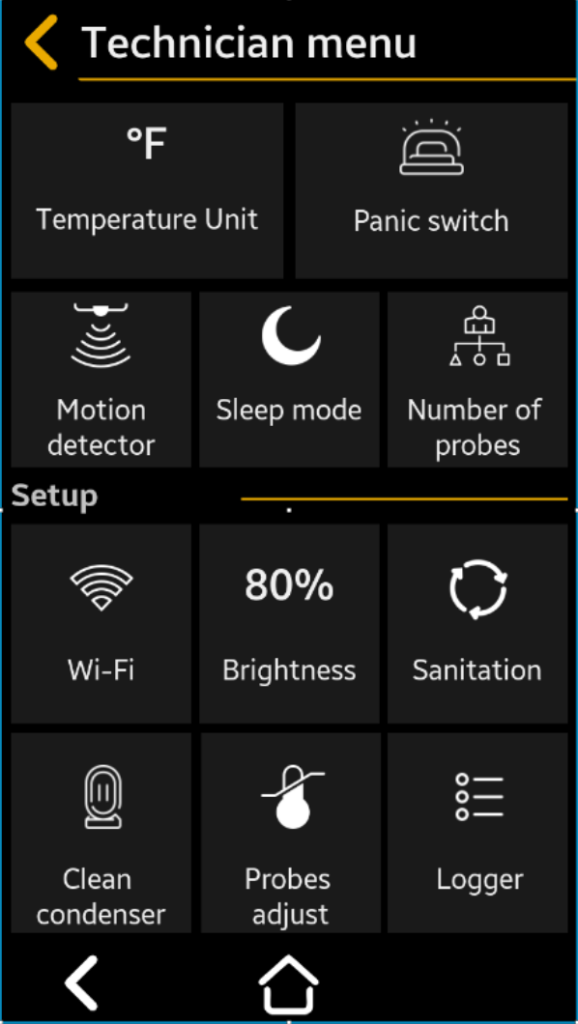
The technician menu is used to set the system, usually when it is installed.
Warning
There is no need to compensate for the cable lengths, because the system uses calibrated digital sensors both for temperature and humidity.
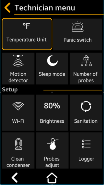
Temperature Unit
Use it to set if the temperature is displayed in °F or °C.
Select to °F (Default) or °C
Press “ Save” to save, then “
 Back” “Back” to cancel the selection
This is example of how values are being modified inside menu sections
Value: 45°C – is the value you want to set your parameter
Value: 999 (Min) & 999 (Max) – represents the interval of the minimum and maximum values.
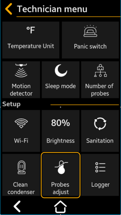
Probe Adjust
Use this parameter to compensate for any differences between the measured temperature at the probe location and the temperature displayed on the TFT (in case the probe cannot be positioned in the exact desired position or in similar situations).
Note
There is no need to compensate for the cable lengths, because the system uses calibrated digital sensors both for temperature and humidity.
Probe #1 Adjust – Select to the desired temperature reading offset, between -10° and +10° if necessary
Default = 0.0°
Probe #2 Adjust – only available if 2 Probes are selected – Repeat as for Probe 1 Adjust
Offset is in °F or °C, according to the Temperature unit parameter
Press “ Save” to save, then “ Back” “Back” to cancel the selection
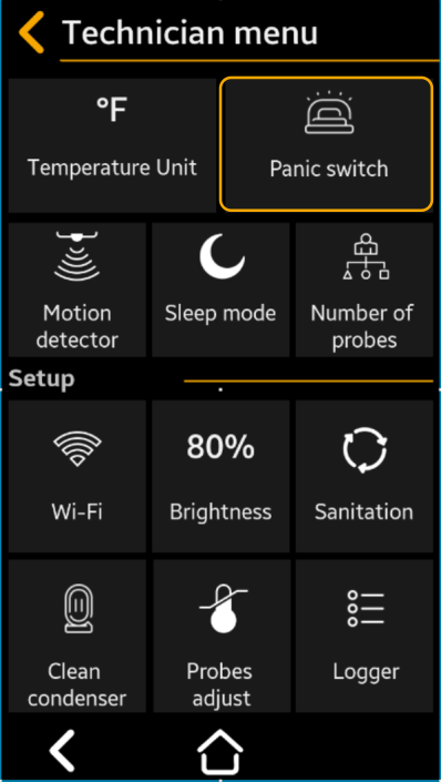
Panic Switch
Set this parameter to Enabled – Yes if the Panic Switch is installed.
Select to Yes or NO
Default = NO
Press “ Save” to save, then “ Back” “Back” to cancel the selection
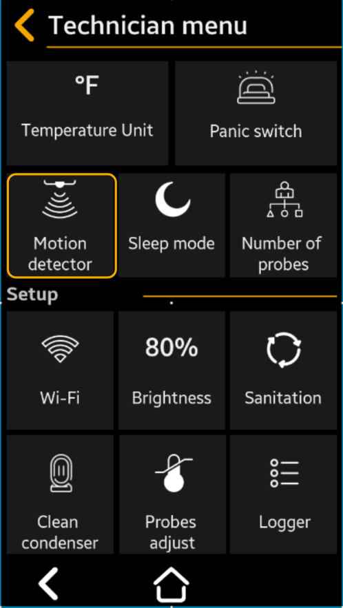
Motion Detector
Set this parameter to Enabled – Yes if the Motion Detector Switch is installed. The motion detector will switch the light on and keep it on as long as motion is detected in the room.
Select to Yes or NO
Default = YES
Press “ Save” to save, then “ Back” “Back” to cancel the selection
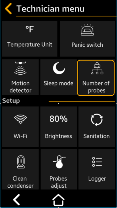
Number of Probes
The number of probes corresponds to the number of rooms to be monitored. One probe can be mounted per room. The probe contains 1 temperature sensor and one humidity sensor.
Select to 1 or 2
Default = 1
Press “ Save” to save, then “ Back” “Back” to cancel the selection
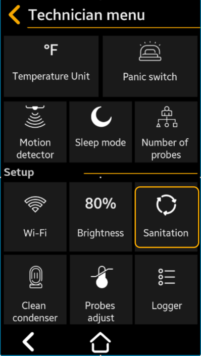
Sanitation Cycle Setup
Use this menu to set up to 30 sanitation cycles. The user can set the cycle start time and duration.Sanitation Cycle Start
Select to Yes or NO
Default = No
Press “ Save” to save, then “ Back” “Back” to cancel the selection
Cycle #1
Start Time – Select to the desired time of day cycle starts
Duration – Select to the number of minutes cycle lasts between 00:00 and 60:00 Format: MM SS Note. Maxim duration can be set to 60:00 (60 min. and 00 sec.)
Cycle #2 – #30 – Repeat as for Cycle #1
Press “Next to navigate to the next cycles screen
Press “ Save” to save, then “ Back” “Back” to cancel the selection
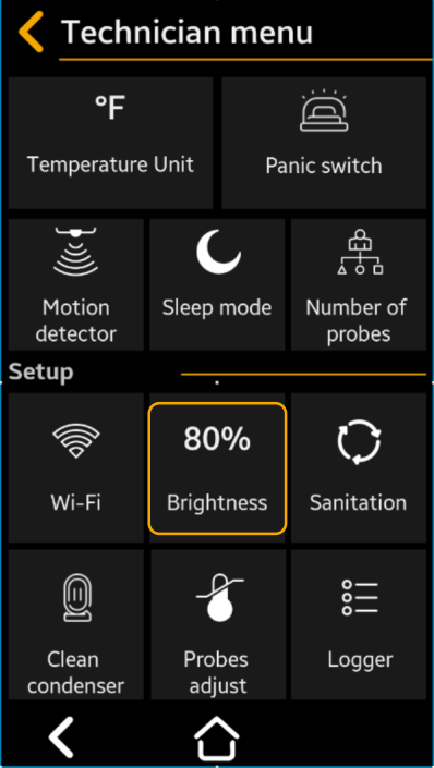
Brightness
This setting allows the user to adjust the brightness of the TFT display screen to compensate for high or low ambient light conditions, or to prolong the life of the display.Select to the desired brightness level between 5 and 100% Default = 75%
Advise
Use 100% when using the room outside.
Using lower brightness levels will prolong the TFT lifetime.
Press “ Save” to save, then “ Back” “Back” to cancel the selection
Wi-Fi Setup
- Enable the Wi-Fi connection for the system
- Setup de Wi-Fi connection
- Visualize the Wi-Fi settings (if already connected)
- To setup the Wi-Fi connection you can use the Smartrite Mobile App, also, but only if the Wi-Fi connection is set to active!
- Visualize device connection information: Device ID and Device Wi-Fi MAC; these information are coded in a scannable QR code, also.
- Use this information to add the device on the server using the Smartrite Mobile app!
Note
You can quickly access this menu from the Home screen, if you press Wi-Fi Connection icon .
Note
You can quickly access this menu from the Home screen, if you press Wi-Fi Connection icon


Wi-Fi Enable
Select the switch button to activate / deactivate the Wi-Fi connection
 = Enabled
 = Disabled (Default)
Press “ Save” to save, then “ Back” “Back” to cancel the selection
Note
If the Wi-Fi is disabled, the connection to the server will be lost, but the last network the device was connected to will still be stored in the systems memory. Therefore, if you will enable again the Wi-Fi connection, the system will automatically connect to the previous SSID. This does not apply if you press the forget button
Wi-Fi Network Information
The system automatically populates the following information: Connected Wi-Fi name (SSID)
Device IP address
Device subnet mask
Gateway IP address
Wi-Fi Signal Strenght (RSSI) indication in dB
If the WI-Fi signal is strong (over -85dB) -> the attenuation value is indicated with green, near the Wi-Fi icon, on the top left of the TFT
If the WI-Fi signal is weak (under -85dB) -> the attenuation value is indicated with red, near the Wi-Fi icon, on the top left of the TFT
This means that the user must improve the Wi-Fi signal near the Smartrite device (place the AP closer to the Smartrite or mount a supplementary AP)
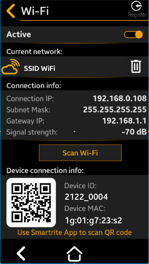
Scan for other Wi-Fi network
Click this button, and the device will scan for the available Wi-Fi networks within its range and show them in a list ordered by signal strength, with the strongest signal shown first.

At the top of the list, the current network (SSID) to which the system is connected is indicated.
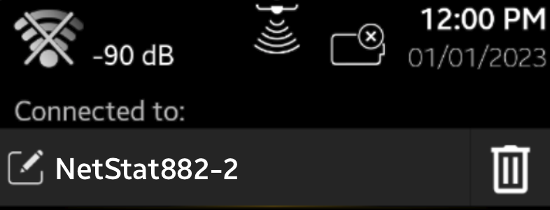
Below that, a list of up to 20 available Wi-Fi networks within the device’s range is displayed. These networks are ordered by signal strength, with the strongest signal shown first.
Click the desired SSID and the device will ask you to setup the connection parameters.
Note
The device only supports 2.4GHz Wi-Fi networks.
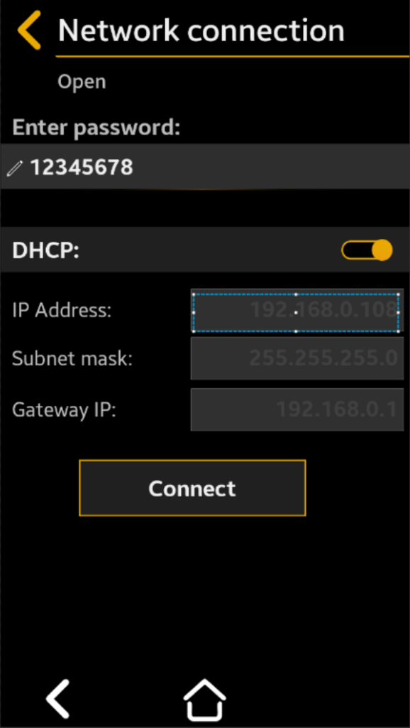
Network connection
Beneath the Network connection title, the Wi-Fi network’s security level is indicated, whether it’s open, encrypted, etc.
- Enter passwordIf the network in encrypted, you are asked to enter the network password
- DHCP
- If DHCP is = Enabled the router will set the connection parameters (device IP address, subnet mask, and gateway IP).
- If DHCP = Disabled the device will prompt you to manually set the Device IP address, Subnet mask, and Gateway IP for the Wi-Fi connection to the router
- If DHCP is
After everything is set, click Connect to establish a connection to the selected Wi-Fi network using the parameters you entered.
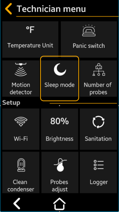
Sleep Mode
he function allows the Technician to put the system into a Sleep Mode when the unit is powered down to conserve the battery. Use this mode during shipment or other extended off periods to conserve battery. To use this mode the system must be operating on battery backup (power off).
Power off the system when you need to work on the electrical wires connected to it. If the system has a battery backup follow up the power down procedure
- Disconnect the system from the mains.
- Turn on the sleep mode: from the TFT access Menu->Sleep Mode
- Select to Yes or NO
Default = No
Warning
If the Wi-Fi is disabled, the connection to the server will be lost, but the last network the device was connected to will still be stored in the systems memory. Therefore, if you will enable again the Wi-Fi connection, the system will automatically connect to the previous SSID. This does not apply if you press the forget button\
Press “ Save” to save, then “ Back” “Back” to cancel the selection
Note
If you will enter this mode with the mains power on, the system will run a hardware reset only
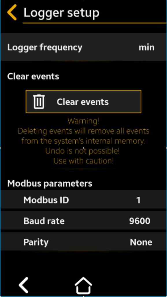
Logger Setup
This screen contains:
- The setup parameter that determines how often the functional data (called periodic events) are stored in the system memory and on the cloud server (if the system is connected to the Internet).
- Clear events function –clears all functional events stored in the device’s internal memory.
- Modbus parameters are used for the device to connect to a PC through the serial connection using the Modbus RS485 protocol.
Note
Over 100,000 periodic events are stored in the internal memory; ALL events (periodic events plus alarms) for 1 year of functioning can be stored on the cloud server.

Logger Frequency
Select to frequency, in minutes between 1 and 60 min., for data collection
Default = 15 minutes
Press “ Save” to save, then “ Back” “Back” to cancel the selection
Clear Events
- Select Yes to No
- Default: No
When set to YES, all the functional events will be cleared from the device’s internal memory.
Note
The events transferred in the cloud will not be deleted using this function!
Press “ Save” to save, then “ Back” “Back” to cancel the selection
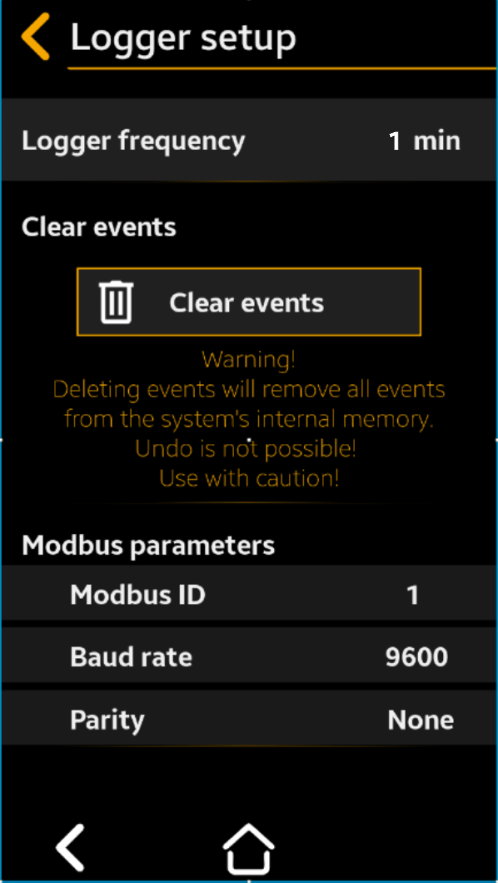
Modbus parameters
- ID Modbus
- Select to choose the desired device serial ID from 1 to 255
- Default: 1Baud rate
- Select to choose the serial communication speed between 9600, 19200 or 38400
- Default: 9600Parity
- Select to choose the communication parity between None, Even or Odd, according to the PC software requirements
- Default: None
Press “ Save” to save, then “ Back” “Back” to cancel the selection
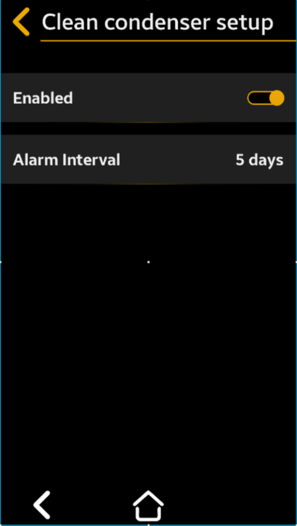
Clean Condenser Setup
This parameter allows the operator / Technician to set a repeating condenser cleaning interval reminder.
= Enabled
= Disabled
Press “ Save” to save, then “ Back” “Back” to cancel the selection
Alarm Interval – Select to number of days (between 1 and 60 days) between cleanings
Default = 30 days
Press “ Save” to save, then “ Back” “Back” to cancel the selection